|
|
 |
|
|
|
|
|
| Measures DC to 10KHz, static or dynamic |
|
|
| Repetitive or transient motion |
|
|
| Tracks displacement, velocity and acceleration in real time |
|
|
| Spectral response comparable to the human eye |
|
|
| Simultaneous multiple-axis or differential measurement |
|
|
| Full-scale measurement range: 0.020 to infinity (lens dependent) |
|
|
|
|
|
|
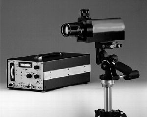 A unique, non-contact instrument for real-time motion and vibration measurement. The image
dissector tube in the optical head converts the movement of the focused target into a fast-responding, non-scanned,
calibrated analog signal, for a process that works even when other instruments fail. A unique, non-contact instrument for real-time motion and vibration measurement. The image
dissector tube in the optical head converts the movement of the focused target into a fast-responding, non-scanned,
calibrated analog signal, for a process that works even when other instruments fail. |
|
|
| Remote Measurement |
- No mechanical loading or change in specimen dynamics
- Measure movement of soft or fragile specimens
- Measure inaccessible objects from a distance
- Measure hostile environmentshot, cold, vacuum, radioactive, high voltage, corrosive, explosivefrom the outside
- Follow very small movements at a distance
|
|
|
| Three different models meet specific requirements: |
- 510 Single Axis Displacement Follower
- 510X Differential Displacement Follower/Extensometer
- 560 Biaxial Displacement Follower
|
|
|
| How it works |
The non-contact, electro-optical Displacement Follower tracks the motion of a target that
has a sharp discontinuity in light intensity, either reflected or emitted. The tracking system
locks onto and follows the light-dark interface.
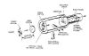
The lens system focuses the image of this discontinuity onto the photo cathode of an image dissector tube
(click for a simplified drawing of this tube).
Electrons emitted from the backside of the photo cathode in proportional to the intensity of the projected
light are then accelerated to refocus on an aperture plate containing a small hole. This converts the optical
image to an electron image, with an electron density is proportional to the light intensity of the target. As
electrons enter the small aperture, they are amplified to produce a current output proportional to the number of
entering electrons. Moving the electron image across the aperture plate causes a change in the number of
electrons entering the aperture.
The system detects change in the output current of the phototube, and through a servo loop is able to cause
the electron image to refocus on the aperture. The servo loop circuit re-enters the electron image by passing
current through coils to create a magnetic field that deflects the electron beam to its original position. The
current needed for deflection is directly proportional to the distance that the electron image has moved away
from center and is therefore a measure of displacement. Since the aperture has a finite dimension, the actual
interface (target) can be moved.
|
|
|
click to enlarge | |
|
|


